About Me

My photo
They never fall who never climb.

Sorry, this blog discontinued.

ANNOUNCEMENT
           This blog will no longer be updated. But I choose to keep it published as a testament to newcomers in electronics; you must persist past the bad and there is a lot of it out there. My conclusion is that 99% of the established electronics learning system is wrong and dominated by pseudo-experts who know nothing about teaching.

           Yes, I am being very critical, but for good reason. Most books on electronics are really bad. With rare exceptions, the easy lessons are too easy and the hard lessons are too hard. They feed you a few fundamentals and leap directly into Star Wars without any of the vast intermediate knowledge and projects you had in mind.

           I am planning a series of short publications which, for the first known time in electronics, stays on topic at every level. Do check back, and thanks for your interest.

Minutes

WHAT THIS BLOG IS ABOUT
or Go directly to Table of Contents


           This is a record of the electronic circuits I’ve experimented with. These are not lessons and certainly not lectures. These are accounts of experiments and therefore both successes and failures are shown. Like many beginners, I have some idea what the individual components do; this is my first attempt to connect them. I have two standards and no idea if those standards are practical:

           1) everything is 5 volts.
           2) Direct Current (DC) only.

ATTENTION: This blog is upside down, that is, the entries read from oldest to newest, just like a real book. Therefore, to see new posts, you have to scroll to the bottom or click on "older posts".

           It is hoped, of course, as time goes by experience will make these reports more comprehensive and elaborate. A conversational style is adopted so that the material has a broader appeal to the average reader. Where an experiment was unsuccessful, it is reported as such and no attempt has been made to sanitize errors. In fact, blunders are often used to generate further experimentation, as it is meant to be.

           In general these records should reveal the learning curve of an adult who is beyond prime “schooling” years. It amounts to teaching an old dog new tricks without any assurance of success or a defined goal. That is part of what is meant by “non-fiction”. Enjoy, and please respond.

           For data entry or display, the Deltacomm™ standard is used throughout this work. Anything to be entered is displayed literally between end braces. If instructed to enter “cow” without the quotation marks, this becomes [cow]. In the Deltacomm™ standard there is no need for clarifying explanations. If the quotation marks were to be entered, it would show as [“cow”] and if the end braces themselves were to be entered, it would show as [[cow]]. Enter exactly what is between the outermost end braces and nothing else.

* * * * *


           An original article by veryatlantic™ (republished from many sources):

There are 27 Letters in the English Alphabet

           One of the first lessons I give to new students is my lecture on the alphabet. The people who created such items as html (Hypertext Markup Language), search engines, and the C series of programming languages were functional illiterates, that is, educated beyond their intellect. They did not grasp the proper usage of punctuation and totally missed the concept of the blank space.

           The blank space is the most frequently used letter in the English language, it generally occurs before and after every written word. It is indeed a letter, if not the most important letter. Those who ignore it have inflicted endless hardships upon future generations. It is as valid a letter as any other, and requires the same memory to store. It is a telling joke of the state of college education that so many learned people never realized its significance.

* * * * *


The C Family of Languages

           For progress to occur, there must be in improvement on the existing system, or an easier method to accomplish the task that was on hand before. In this sense, the C language, which includes C+, C++, etc. represent a retrograde step, a backward evolution to a more crude system of computer commands. It is not uncommon to spend twice as much time looking for a missing punctuation mark as to actually create the C code.

           First of all, the C language is not new and those who claim otherwise are poor students of history. Every functional command in the C language was copied from good old BASIC, Fortran and COBOL. C has not introduced a single new computer command in its entire life. Everything from variable declaration, loops, if-then, and the math commands were old thinking by the time C arrived. True, there are certain library and machine commands available to C, but these were made needlessly complicated.

           I propose the following guidelines to judge whether any new computer language is, in fact, an improvement. If a language does not meet these rules, it hardly represents an advance in thinking. The following are called the Deltacomm Criteria:

  •       1. Capitalization is universal. A capital letter is not the same as a case letter. Ever.
  •       2. No command is more than 8 keystrokes long, nor requires any double-keying (no shift key, control key or alt key).
  •       3. All commands must be alphabetic and self-explanatory.
  •       4. Minimal use of punctuation, never more than 2 punctuation marks in a row, never more than 4 punctuation marks in a command line, formulas excluded.
  •       5. No spurious or misleading words such as “void” and no embedded capital (camel-hump typing) unless the programmer deliberately includes them as an option.
  •       6. All print strings are literal, never containing non-printing punctuation. Print (“Hello World”) must print (“Hello World”) including the brackets.
  •       7. The most common print command will include a line feed by default.
  •       8. Concatenated strings will automatically insert a space by default.
  •       9. Commands must have a consistent and predictable default behavior.
  •       10. All command lines must end with a consistent marker, no exceptions.
  •       11. Programming structure should have a simple indentation structure that clearly reveals nested loops and overall code organization.
  •       12. All languages should accept line numbers as an option to the programmer.
  •       13. Variables and subroutines become local reserved words making it unnecessary to place them in parentheses in the body of a program.
  •       14. No programming language shall use any expression, abbreviation, initialization, or term that has another contemporary common usage. Eg. “IDE” for both a hard drive cable configuration and a code editor was just a dumb thing to do.
  •       15. No dot notation. Dot notation is an experiment that failed.
  •       16. Methods, procedures, and properties are called commands, which is what they really are in the first place.

               It is clear that using these reasonable principles, the C language is a miserable failure. I wonder what the creators were thinking, how they ever hoodwinked the community into adopting such a system. I am convinced they did it as a joke and it got away on them.

    * * * * *


    Disclaimer: this work is intended for entertainment only and not for technical reference. The entire publication and its several parts is/are copyrighted to the maximum extent of law and the sole property of Deltacomm™ or its associates. If you act upon the material presented here, it is at your own risk. The author is not responsible for any damage of any type resulting from any usage under any theory. This work is published without prejudice. Fair usage quotations are allowed providing the source reference contains at least the word “veryatlantic™”. Any reference to gender, tense or plurality in this composition shall be interpreted in favor of the author.
  • 000 TABLE OF CONTENTS


    000 TABLE OF CONTENTS


    Experiment 001 Simple Current Direction Indicator

    Experiment 002 Voltage Regulator (7805)

    Experiment 003 Resistor and LED Brightness Experiment

    Experiment 004 Improved Voltage Regulator

    Experiment 005 Hello World Blink LED

    Experiment 006 Microprocessor Controlled LED Fade In/Out

    Experiment 007 PWM Voltage Amperage Test

    Experiment 008 Test Serial Input/Output Feature

    Experiment 009 Simple Radio Circuit

    Experiment 010 Potentiometer Tests

    Experiment 011 Test Random PWM Values with LED

    Experiment 012 Array-Based LED Control

    Experiment 013 Test Arduino Math

    Experiment 014 Bicycle Blinker Light Array

    Experiment 015 Digital Switch Behavior

    Experiment 016 Spin Motor with Transistor Control

    Experiment 017 Spin Motor with Sensor Control

    Experiment 018 Home Made LED Dot Matrix 3x3 Display

    Experiment 019 Keyboard Matrix Control

    Experiment 020 Piezo Sound Test

    Experiment 021 Transistor Controlled Single LED

    Experiment 022 Seven-Segment LED Display - Single Digit

    Experiment 023 Seven-Segment LED Display - Double Digit

    001 SIMPLE CURRENT DIRECTION INDICATOR


    001 SIMPLE CURRENT DIRECTION INDICATOR

    JANUARY 1, 2011    (See also Companion Blog )

    [Go BACK to Table of Contents] [ Next Experiment ]

               This wiring represents a “simple current direction” indicator. That is a logical place to start, as it is a circuit that shows some smarts beyond making a light turn on or off. My crude diagrams should get better as I learn. Meanwhile, I have to leave out things like resistor values.


    Theory:
              As current flows through the circuit, only one of the LEDs will light up. The LED on the right is green, the one on the left is red. The diodes are unidirectional and you can see they are reversed. If current is flowing in the correct direction, the green LED lights up. If in the wrong direction, the red LED will light.

    Practice:
              Nobody told me the resistor was necessary to limit the current flow, so I burnt out a diode. You cannot tell if a diode is burned unless you test it, later I learned it has a characteristic aroma. If you don’t see it blink off, you can easily waste 15 minutes trying to figure out why nothing works. The circuit does work, with the green LED indicating correct polarity. But when the polarity is reverse, the red LED comes on momentarily, then shuts off. I can find no reason for this behavior.

               I had much more difficulty than I should have figuring out how to wire the diodes in parallel on an ordinary breadboard. Obviously, I need to know about resistors more, I don’t know why the resistor here was placed away from the current source, but my reading indicates this is not important.

    Conclusion:
              Although the experiment was not perfect, I will leave it and move on. I have decided not to use this circuit until the red LED problem is solved.

    UPDATED March 28, 2011
               See the difference three months experience can make? I went back, rewired this circuit exactly as I did or thought I did, and it worked perfectly today. There is no Arduino code, this is a hardwired design that eventually taught me four important concepts.
               A) buy store-bought jumper wires, don’t make your own
               B) learn to visualize the breadboard wiring instantly
               C) every error is a design error, a pilot error
               D) a burned out LED has a characteristic aroma

    It may have also taught me the need for a decent macro camera. I’ve passed the stage where written descriptions can cover the same ground. Here are my blurry photos this circuit, in regular and reverse current modes. I had to swap a yellow LED for the original green as the millicandelara of the green made it much to dim in ordinary room light. Since the LEDs shared a common resistor, it made more sense to change the LED.

    Here is the circuit in both modes, blurry but better than no photo at all.


               So you know, the original resistor was 1KΩ but that was too strong to allow a green LED to light at all. It was replaced by a 330Ω. This is shown below. The green LED is on, but barely visible on the center circuit. Be aware there is more than one circuit on the breadboard shown, but they have been intentionally smudged.


    Go BACK to Table of Contents

    002 VOLTAGE REGULATOR (7805)


    002 VOLTAGE REGULATOR (7805)
    JANUARY 7, 2011    (See also Companion Blog )
    [Go BACK to Table of Contents] [ Next Experiment ] [ Last Experiment ]


               This is a 7805 voltage regulator, apparently a very common item produced by the millions. Again, I leave out values of things like capacitors. This complicated looked circuit (for me) took a while, as I didn’t grasp the fact of the common ground.


    Theory:
              Any voltage from 7.5 to 30 Volts fed into the 7805 will emerge as a steady 5 volts, with the excess being radiated away as heat. The capacitors are to smooth out any fluctuations in the input and output currents, or voltages. The input is a big capacitor, the output is a small capacitor. I don’t know why.

    Practice:
              The 7805 has three pins, the middle one being a common ground. To me, this meant the voltage came out of the regulator “upside down”, that is, the positive lead is the opposite side of the ground from the input lead. Look at it for a second, you’ll see what I mean. I don’t know the symbol for a voltage regulator, but it sort of looks like what I drew, with the little hole for mounting a cooling fin for larger voltages.

    Conclusion:
              This circuit worked out perfectly. The input voltage was 12.3V and the output was 5.0V although the specs said this could vary between 4.75 and 5.25. It was bang on. I even tested it with the current direction diodes from experiment 001. I’ve left it installed on my tiny breadboard as it only takes up three rows of pins.

    Update 2012-04-27
              I finally built my own version of this handy circuit. Looking back, I realize the absolute need to combine theory and practice in short, coordinated settings.  Building small projects like this is more than important when getting started.  Here is a photo of the circuit shown above, but with an LED added to show when it is operating.  The board rests on a small piece of dry sponge to make it handier when I'm working with bare wires.
              Now when I say short learning sessions, I've found it best to go out and build something almost as soon as you learn the theory.  This tiny circuit taught me more than any of the $60 text books I studied at first.  I grasped the concepts, but until I built this circuit, it was a struggle to get anything to work.  I'll write out the things I believe were most important.  First, here is a photo (I still don't have a macro camera).

              A) notice the tight grouping of the components.  This is a weird departure from the layout used on your breadboard.  When you flip the circuit over, you must learn to think "backwards" to keep organized, especially with parts that are polarized.
              B) you can't see the reverse side, but how strange that there is no convenient way to make the connections.  You can solder connecting wires, which is a messy process more trouble than it is worth.  I bent the component leads together wherever possible, and used blobs of solder where possible.  There is a trick to doing this right and you can't learn it from a lecture.  Just do it.
              C) those blue connectors were an afterthought.  I was not sure how I would use this circuit, but these screw terminal type connectors let me use solid wire, stranded wire and standard breadboard connector pin wires.  But I would not use them again, since you always have to hunt for a small slot screwdriver.  Again, learn it by doing it.
              D) this circuit was one of around a dozen separate "parts" I constructed and now use as modules for other experiments.  This is wiser than building anything complicated on a larger board, and building this first 7805 power supply taught me that.  The most expensive component was that yellowish capacitor, which seems to make absolutely no difference in the performance.
              E) you gain an appreciation of what things cost.  Some well-funded individuals may disagree, but if you are on a budget, you learn to work better when building things like this circuit. Sometimes you learn that a ready-built item already exists and costs less, but you continue anyway for the learning.  I've yet to see a major author that spells out this extremely important factor--the average guy will always run out of money before he runs out of project.
              F) if, like me, you could not solder before, you will learn fast on these early attempts.  I was too shaky, too ham-handed, and kept touching other parts.  You quickly recognize the aroma of fried parts--but keep at it, I assure you later it will become fun.  It took me some six hours and an estimated 40 failed solder attempts to get this one frustrating thing to work.  I won't say how often it looked perfect and still just sat there.
              Keep at it, one year later I can solder just about anything successfully on the first try.  And this little gizmo is where I started.
              It's kind of grainy, but here is a photograph of the club using some of the little circuit boards I made like the one above.  Shown here is a 555 timer circuit and a transistor switch being to used to test the operation of a store-bought car stereo board. Note both are built on pre-fab circuit boards like the kind you buy at the Shack. See also the 12V motorcycle battery in use. It cost $35. But you'll quickly tire of dry cells when you want to get some serious work done.


    Go BACK to Table of Contents

    003 RESISTOR AND LED BRIGHTNESS EXPERIMENT


    003 RESISTOR AND LED BRIGHTNESS EXPERIMENT
    JANUARY 13, 2011    (See also Companion Blog )
    [Go BACK to Table of Contents] [ Next Experiment ] [ Last Experiment ]

               This circuit was complicated by my inability to clearly visualize parallel breadboard circuits. Part of the purpose of this configuration was to finalize the concept in my brain.


    Theory:
              LEDs arranged in parallel with differing resistors should glow brighter or dimmer, depending on the total resistance. Thus, I chose six identical resistors, and wired them in strings of one, two, and three. At the end of each string is a LED. Look at this diagram. To me, it is obvious the last LED should be the dimmest.

               When the power goes on, the brightest LED should be the leg with one resistor, next the LED with two, and the dimmest should be the LED with three. I also wired the breadboard so that there was a bare wire test point between each resistor to test the “voltage drop”.

    Practice:
              Nearly complete failure. The circuit lit up first try, but the brightness difference, if any, between the second and third LED was not distinguishable. I tried repositioning the LEDs in case there is such a thing as a bad one. No difference. Then I tried a different color. Still no difference.

              Yet, there is a distinct difference in brightness with the one-resistor segment, therefore there must be a current difference in at least that leg. Why? Possibly the equation is non-linear and I need a far higher resistance on the third leg? The voltage across all three legs was 5V, so the lights should vary considerably since I used large (4700Ω) resistors. Either my thinking or the wiring is wrong. Soon, I will repeat this experiment using different resistors.

    Conclusion:
              I don’t know enough about resistors and how they function in parallel circuits. I should try this experiment again in a series arrangement. Actually, I would be happy if it turns out my logic was exactly opposite instead of somewhere in between, to show at least I was trying to think. The good news is I used the 7805 voltage regulator and am encouraged to solder a permanent supply. Later: if you go back and read the update to Experiment 2, you'll see I did just that. And it's a nice power supply, too.

    January 27, 2011 (Update)
               This experiment was repeated and for unknown reasons, partially successful today. Instead of resistors in series, I now have different resistors and I used 330Ω, 1kΩ and 4.7kΩ, all in parallel LED segments similar to the above. This time, I used the Arduino 5V supply and the Arduino ground. The LEDs lit up as expected, with the least resistance the brightest. Then for unknown reasons, the Arduino would die, that is, lose its communication with the computer and drop the communications port (Com 6 on my equipment) after a few seconds. It did this fifteen times.
               As for the experiment, my original wiring or components were likely wrong. I suspect it takes an extremely high resistance to make a visible difference in brightness for the higher ratings and I would probably need a 10kΩ resistor to test this adequately. I now rate this experiment a success and the file closed.

    May 1, 2011 (Update)
               I was finally able to return to this experiment with the proper equipment, experience and knowledge to make it work. Here is a photo of the seven LEDs now varying in brightness due to gradually increasing resistors from left to right.

    Later experience:
               This circuit does not use the Arduino as a power supply, rather a good old 9V battery. I now understand that that the Arduino does not supply power continuously in every situation, that often the supply is dependent on the Arduino calling the correct pin continuously from within a loop, which is more trouble than it is worth for an analog experiment. But I had to learn it, so the effort was worthwhile.
               Return later for details on how to duplicate this experiment.  <<< I wrote that in haste.  I think even a beginner should now be able to conduct this experiment without any panic.  I leave the description as is so that you know even a schmuck like me can get it to eventually work.  It is nothing but resistors and LEDs in parallel.  It was months later I learned parallel is the way to get the same voltage (not the same current) across every leg of a circuit.  Now, I have some choice words about voltage drops.  Read on.

    April 27, 2012 (Update)
               Once again, the so-called "expert authors" left out so many important details that I no longer believe there is such a thing as a decent beginner's electronics manual.  I say, dig some money out of your pocket, buy enough to get you started, and be prepared to mess up and destroy things.  That's how I made the above experiment work, and look so nice, all wired cleanly and looking pretty.  I dropped pieces, lost pieces, stepped on them, burned them out, burned my fingertips and drew blood on their leads.  If you don't do the same, question your progress.
               Gee, look at all the meters.  Yeah, well I read so much crap about voltage drops that I didn't know who to believe.  The only thing the experts consistently got right is that the total voltage drop adjusts itself across all the components in the circuit to reach zero by the time you get to ground.  You don't have to go through the same trouble I did, but that's how frustrated I was by writer after writer talking down to me about things I was magically somehow supposed to know.
               I won't detail my findings, but you can see from the following graphs that the voltage drop occurs in different places along the path.  Here all I did was place the resistors before the LED in case A, and after the LED in case B.  I had some baffling readings until I built the basic circuit shown in this experiment and did these measurements for myself. Is is important?  I don't know, but I do know it caused me tribulation and was not even mentioned by the professionals.  To be honest, I am sick and tired of all the half-baked authors out there who don't proof-read their own work and make getting started in electronics far more frustrating than it should be.  They are there to sell books, not to teach the right things.

    004 IMPROVED VOLTAGE REGULATOR


    004 IMPROVED VOLTAGE REGULATOR

    JANUARY 15, 2011    (See also Companion Blog )
    [Go BACK to Table of Contents] [ Next Experiment ] [ Last Experiment ]

               This is the same voltage regulator as Experiment 002, but with the addition of a switch and a light. There are also two commercial binding posts at the output side to connect to the external wiring. Not shown is the 15V transformer from an obsolete cell phone. This diagram is the part that I built.


    Theory:
              The circuit contains a switch, which I now know is called a STSP, or single pole single throw. When the current is turned on, the (yellow) LED will glow and the 7805 Voltage regulator will supply 5.0V. Some thinking was required to position the switch, and I decided to place it sequentially after the input capacitor. In my thinking, this means the incoming current is smoothed before it gets to any working components.

               This makes the LED a more trusted indicator of current actually reaching the 7805 (voltage regulator) than placing the LED anywhere else in the circuit. The reason for chosing a red LED is that they are the most common, the cheapest, and use a very small current compared to blue, green and other colors.

               Yes, I almost forgot the resistor, again. It is positioned so that any limit it places on the input current occurs where there is most likely to be a surplus. I also placed the indicator LED ahead of the 7805, because placing it on the output side would draw away some of the 5V and I didn't want that. The reason for the LED is also because I don't yet trust switches by themselves. I want to see the power light up the LED, not just a switch in the "on" position. I wonder where and how one would connect an output meter to this circuit. Is it supposed to be obvious?

    Breadboard:
              This is where I would include a photograph of the breadboard if I had a decent camera that could take such pictures.

    Practice:
              The store-bought LED switch turns out to be unsuitable for this circuit. It was permanently lit by a separate 1.7V supply and the LED did not indicate if the switch was on or off. I had to replace it with an ordinary toggle switch and LED. It took almost two hours to solder the first three components and I overheated several parts of the substrate (generic PCD board). There must be a better way.

    Conclusion:
               I need more practice on the soldering iron. And maybe to write some decent soldering directions that avoid the COIK syndrome, which I just used. COIK = “Clear Only If Known”. Since this circuit was fully functional on the breadboard in two different patterns (but same configuration), I put it on hold until I can reliably solder every joint every time, like the man on the video.

    Updated January 17, 2011
               Later it has been determined that none of the instructions on soldering contained a warning about the heated iron touching the substrate. Several of the diagrams showed the iron doing just that. Thanks a lot for nothing. Apparently touching the substrate is not necessary, as the heated solder will flow down the component lead and the solder flux will allow the solder to adhere to the circuit board. Testing is underway but that's the last time I trust a so-called bunch of experts.

    Updated April 24, 2012
               I built this circuit for demo purposes only, and quickly dismantled it to salvage the parts. The switch that worked was expensive ($3.60). Oddly, it costs extra to obtain a switch with the pins spaced so as to fit on a standard breadboard. That's a "duh", America.
               Below is a comparison photo of the difference in how I've learned to solder, the two photos are about eight months apart. They don't represent this circuit, rather show the experience gained after ruining plenty of work by following the wrong directions.

    Go BACK to Table of Contents

    005 HELLO WORLD PROJECT - BLINK A LIGHT EMITTING DIODE


    005 HELLO WORLD - BLINK A LIGHT EMITTING DIODE

    January 22, 2011    (See also Companion Blog )
    [Go BACK to Table of Contents] [ Next Experiment ] [ Last Experiment ]

               This is the first circuit recommended for all beginners with a microprocessor. I’m going to pirate the schematic, since the entire wiring consists of placing a single LED into two pins on the Arduino Uno. The documentation states that pin 13 (a true digital output) has a built-in resistor, so it is not necessary to remember to include the resistor to prevent burning out the LED. Ahem.

               You are expected to know that the diode is directional, that the A lead is longer than the K lead, and what all this means. I am not including the computer code here as this example is trivial and I have not yet decided on what standard to use.


    Theory:
              The LED is connected to a microprocessor instead of a relay, switch or other standard controlling device. The microprocessor (Arduino Uno brainboard) is in turn connected to a computer. Various compatible commands (known as “sketches”) from the computer are “uploaded” to the microprocessor. The LED should blink in a fashion determined by those computer commands.

    Practice:
               The circuit performed perfectly, after several fitful starts concerning certain behaviors and operations of the microprocessor that were not detailed in the product documentation. Initial code made the light blink on and off at intervals of 300 milliseconds. The variables in the code were changed to experiment with intervals down to 20 milliseconds, where the individual flashes became too rapid to detect, up to 600 milliseconds with dozens of intermediate values for both “on” and “off” cycles.

    Conclusion:
               A successful first attempt, which although simple in concept, was a major step forward. Dozens of undocumented but essential aspects were force-learned. Most important appears to be how the brainboard remembers uploaded code when the USB cable is removed. This means there is some power source on the brainboard that is not mentioned in the manual, which also means it has a maximum shelf life.
              Secondary conclusion: microprocessors are a hands-on adventure, lose the book for a while and get a microprocessor on your workbench as early as possible. Biggest lesson: develop a filing system to match your schematics to the your sketches, or you’ll meet with woe.

               This experiment matches Arduino sketch A100401_01BlinkLED in my files.

    Update April 26, 2012
               You will find this same "blinky" experiment repeated ad nauseam on the Internet. Guys. It's been done! There's a real accomplishment to getting it working, since you must have mastered a number of skills unrelated to programming. Like downloading and installing the code processor (I think nerds call it an "integrated development environment" to confuse it with other IDE meanings). You'll have made port settings, and be able to find your way around the Arduino, no mean feat for the complete beginner.
               But after that, there should be a reward posted for somebody to come up with anything new at the novice level. As I progressed through ever more complicated Arduino code, I began so suspect a conclusion that is not addressed in the available material. Hypothesis: can the Arduino can be programmed to duplicate the operation of any combination of discrete components and logic gates? Here is a quad NAND gate I built before programming the same operation using four simple IF-THEN commands.
               This idea still has me thinking deeply. Do I focus on learning more code, or do I devote any more time to learning how components work? For example, I still don't know how induction works, or how to calculate the correct current for a transistor base. But is all that needed if the Arduino can do the same thing with code? Whether my hypothesis is right or wrong, why isn't there a body of text that spells this out?

    Go BACK to Table of Contents

    006 MICROPROCESSOR CONTROLLED LED FADE IN & OUT


    006 MICROPROCESSOR CONTROLLED LED FADE IN & OUT

    JANUARY 23, 2011    (See also Companion Blog )
    [Go BACK to Table of Contents] [ Next Experiment ] [ Last Experiment ]

               This circuit represents my first “thought out” project, as I could not find the corresponding schematic. Here is the schematic, which focuses on matching what the wiring actually looked like rather than for neatness. My intention centered on the code, not the electronics. Sketch is A100414_03FadeLEDinout.pde. Schematic is Components.xls Worksheet 006. See, I’m learning.


    Theory:
              The diode should fade in and out rather than blink. The code contains a loop that counts up and down from 0 to 255, using this counter as a variable to determine the voltage (I think it is voltage) to the LED, shown here as an ordinary diode. By changing code values, the fade should be controlled in a variety of settings.

    Practice:
               A perfect operation. My mental spotlight was on the code, but that is expected. Once the predicted fade was accomplished, I changed the code to find approximately twenty patterns which I would rate as ranging from pleasing to annoying. A little practice with the board reset button shows the code always begins from the programming loop, not the position where it left off.

               There are a variety of coding options that produce the same net effect, I won’t go into it. There is far more flexibility in the code than in the circuit wiring. That’s an important lesson.
               This circuit also taught me that, for now anyway, the power that operates the components must come totally from the Arduino board, as the signals control the power and nothing else. An external source won’t work. For now. I found a drawer full of old but matching power transformers, which were used to test and prove the Arduino has a non-volatile memory (the code stays put when the power goes off). The unit is also very tolerant of voltages at least up to 9V.

    Conclusion:
              These trials are critical to the understanding of how the interface between code and component must operate. It is not always a direct cause and effect, as subtle differences are always appearing. As an example, set the delay between the counts (0 to 255) to zero milliseconds and watch what happens to the LED. There are too many subtle facets to write down, you must perform these experiments yourself to get the full benefit.

    Go BACK to Table of Contents

    007 TEST SERIAL INPUT-OUTPUT FEATURE


    007 TEST SERIAL INPUT-OUTPUT FEATURE

    January 24, 2011    (See also Companion Blog )
    [Go BACK to Table of Contents] [ Next Experiment ] [ Last Experiment ]

    007 TEST SERIAL INPUT OUTPUT FEATURE

               There is no brainboard wiring in this experiment, other than an LED in pin 13 to show that the circuit is working. The entire experiment is controlled by the code below and the purpose is to familiarize myself with the Serial read and write commands as interpreted by the Arduino code once it is uploaded. Shown here is a composite photograph that never actually appears on your computer monitor, as will be explained.

               Code matches sketch A100445_SerialReadWrite.pde.

    Theory:
               The code is designed to read any keypress from your computer keyboard. It then adds one to that value and displays the results. An LED on pin 13 blinks to show that the circuit is operating.

    Practice:
               Worked almost perfectly the first trial. The LED did not blink and if you’ll read the code, you’ll see the commands to make it work are considerably more complicated than the simple “Hello World” blink of experiment 005 described above. The modular box shown above was never mentioned in any of the text examples, so this may be a new feature of the Arduino Uno board.
               The box is certainly useful and a considerable improvement over the examples which show the output as scrolling past in that tiny black rectangle below the IDE code box. As shown here, I typed the phrase [Now is the time for all good men] and the lower text box displayed it back as a series of the next consecutive characters. I also tested it on punctuation and numbers with the corresponding same result.
               In real life, whatever you type in the upper box disappears when you click on the Send button, hence the photo shown here is contrived to demonstrate the effect. The results cannot be cleared and cannot be copied. There is no carriage return and long strings flow past the right margin. There is a newline control displayed but it either has no effect or converts the [/n] command to the meaningless [0o].

    Conclusion:
               Much is left to think about. I learned the abbreviation for the microprocessor board is MCU. I see that all the serial data is interpreted as ASCII bytes, which is why the code can display the next consecutive value from the ASCII table (also called the collating sequence). If it sees an A, it echoes back B and so on.

    Questions:
               What is not known? First of all, the directions said use one character at a time, but I typed in strings of characters. How did the Arduino know to read the next consecutive unread character? Put another way, how did it know the last character had already been read. When I typed in two batches, how did it know to append the second batch? Can it only read ASCII code? How did it ignore non-printing characters I typed which were also ASCII code (like the down arrow and control-D)? It is clear all these instructions are built into the unit, but should they not explain this a little better?

    January 26, 2011
               Examining the program module concerning the LED leads me to believe there is at least one line of code missing. There is no condition that sets the LED to high. I’m now suspecting the original code listing which is split between page 41 and 42 in the manual. It is a poor-man’s e-reader, the booklet scanned as a pdf file.
               Moments later, although this did not turn out to be the problem, it sent me in the right direction. A typo in my original code had set the blink interval to 10, too fast to be seen. The code now works perfectly as described, although I don’t quite grasp why the LED flash instructions are so complex. I think it is so the LED flashes regularly despite the interrupts caused by the Serial commands.

    March 27, 2011
               Examining the code after several more trials, I've concluded that it really does work as terribly as I thought, and I thought it was a mistake. The Arduino display is proof that computers are so simple, retarded people who can neither spell nor type can program them.

    Here is the code:

    /* January 25, 2011.
    * First attempt to use Arduino serial monitor.
    * This example found in "Making Arduino Toys Talk", page 41.
    */

    /* This program takes incoming serial data, adds one to that
    * data and sends the result back. There is a blinking LED pin
    * to show the operation is working.
    */

    // Assign variables
    int LEDpin = 13; // use the built in LED
    int inByte = 0; // storage location for incoming data
    long vBlinkTimer; // keeps track of last LED off state
    int vBlinkInterval = 1000; // LED timer
    // End of assign variables

    // Begin Main Program

    void setup()
    {
    pinMode(LEDpin, OUTPUT); // set pin 13 to output
    Serial.begin(9600); // configure serial port
    }

    void loop()
    // check if there are any serial bytes to read
    {
    if (Serial.available() >0)
    {
    inByte = Serial.read(); // if so, read the first byte
    Serial.print(inByte+1, BYTE);
    }

    if (millis() - vBlinkTimer >= vBlinkInterval / 2)
    {
    digitalWrite(LEDpin, HIGH); // light LED pin 13
    }

    if (millis() - vBlinkTimer >= vBlinkInterval)
    {
    digitalWrite(LEDpin, LOW);
    vBlinkTimer = millis(); // reset the timer
    }
    }

    // End Main Program

    //////////////////////////////////////////////////////////////
    // I found the timer code more interesting than the serial. //
    // although I never could get it to work right. //
    // Keyentered January 25, 2011 by da Bassguy. //
    // Uploaded and tested same date. //
    //////////////////////////////////////////////////////////////
    // Note my convention that variables assigned initial values//
    // are given cryptic names, but variable which are to //
    // contain input or output values always begin with a "v". //
    // That's a Deltacomm™ standard. //
    //////////////////////////////////////////////////////////////

    Go BACK to Table of Contents

    008 TEST READ OF A PHOTORESISTOR


    008 TEST READ OF A PHOTORESISTOR

    January 25, 2011    (See also Companion Blog )
    [Go BACK to Table of Contents] [ Next Experiment ] [ Last Experiment ]

    008 TEST SERIAL READ OF A PHOTOSENSOR

              This experiment accepts the premise that all sensing devices in common usage operate on a varying voltage (as opposed to current). I accept for now that at time some other signal may be used, but experiment 007 above consistently failed to measure any changes that I could measure except in voltage.
              I propose to test in two phases here. The first is a simple circuit that confirms a photoresistor can vary the brightness of an LED. I have found contradictory accounts of whether the photoresistor drops or climbs in resistance as the light gets brighter, hence we put it to the test once and for all. The inherent fault with this experiment is that I have to shine a light on the photoresistor and at the same time keep the LED in the relative dark to see it operate. I’d like to substitute a buzzer, but I don’t have one.
              If the first stage is successful, I will then devise or pirate code to determine the best way to have the Arduino IDE serial monitor display the changing values, intending to find a way to permanently record those values.


    Theory:
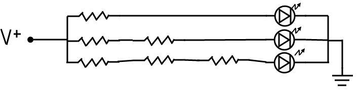
              Any change in the amount of light falling on the photoresistor should cause the voltage through the LED to change, varying the brightness. Note the inclusion of R1 in the circuit (any resistance will do, I used 4700Ω). That is my insurance policy against burning out yet another LED. Hint: use your yellow LEDs for testing as they have practically no use in the real world and so what if they burn up? For convenience, I used a 9V power supply where 5V would have worked fine.

    Practice:
    Phase One:
               Instant success on Phase One. The photoresistor definitely allows more voltage to pass as brighter light falls on it. In an effect I do not yet understand, the resistance across the photoresistor shows no change, and even less intuitive is that the voltage across the photoresistor pins drops as the source light gets brighter. Hold that thought for later.
              The effect is instant and the photoresistor is very sensitive. I tested two photoresistors, a big one and a small one. The big one had to be completely encased in darkness before the LED went out. The small one easily turned it off in partial shade.

    Phase Two:
              The only change in the circuit is that analog read code is connected to this circuit between the photoresistor and the LED, see diagram. The code should detect and read the varying voltage (or other signal) just before it reaches the LED. Here I met with failure. I adapted code for reading potentiometer values and the code has been triple checked. Either I am missing something or testing the wrong thing.
              Read the code below, where I even used an old programming “You are here” message to confirm at least part of the code is working. I even divided the variable value by 5 to ensure the read isn’t out of range and still nothing. The test works the same even when the test lead is removed from the breadboard. For some unknown reason, my apparatus failed to read the sensor values from the photoresistor.

    Conclusion:
               I realize afterward that Phase One could have been performed by attaching the multimeter probes directly to the photoresistor. When I did that, the resistance changed from 120,000Ω in darkness (enough to turn the LED completely off) to 1,400Ω under a very bright flashlight. But then, I would have missed that inverse voltage effect discovered here, wouldn’t I? You might want to be careful that the analog pins are numbered in the opposite direction than the digital pins. Ahem.
               Later, this code and various similar sketches has been checked and double-checked, I am up against some other problem than the code. All the code tested contains a common command to read the analog values from the variable resistor (analogRead(Input);). The values displayed on the serial monitor are nonsense, but in each case it is the same nonsense. This read command, or something to do with it, is the hurdle. Not shown here is how I separated the input and output circuits onto two breadboards to isolate the steps and still got the same results.

    UPDATED March 26, 2011
               I’ve found a partial answer to the failure of my measurements. The sensitivity of the photoresistor is determined by the size of the resistance in the circuit, as the circuit behaves like a voltage divider. All of the resistors I tried had too large a value to cause significant changes in the readings. I watched a video from element14.com where a guy named Blum manages to talk for 15 minutes about the changing values picked up by the Arduino without actually saying what those values represent.
               They represent neither volts, nor amps, but a reading based on samples of the changing voltage. (This range is called the “resolution” so you will confuse it with photographs and a half dozen other meanings.) For those that have to ask or didn’t know enough to ask, element 14 is silicon and you are probably reading the wrong blog as well.

               I was a little unclear on the concept that the photoresistor was analog and could only be read by an analog pin. This completely trounces my chances of getting into Yale. However, the experiment is now a success. Here is the updated schematic. I am beginning to notice the commonalities in sensor reading circuits and have decided to read up on voltage dividers. See how the A0 pin is “tapped” into the circuit to read the voltage between the sensor and the fixed resistor?

    New conclusion:
              This is a lesson I learned the hard way. Once working, the circuit actually performed better than some of the lessons and diagrams I had learned from. For instance, the readings taken were between 330 and 830, a range of 500 on a scale of 0 – 1023 (known as a ten-bit reading). Also, I confirmed the photoresistor drops in resistance as the light gets brighter, but causes the reading to get higher indicating it is measuring voltage rather than resistance.
              I tested further by changing the size of LED, which made a significant difference, the larger the LED the less brightly it shone. In this circuit, the Arduino is not controlling the LED brightness, rather the LED is wired onto the breadboard. Thus, I did not test the LED by using pulse width modulation (PWM), for that see experiment 017.

              However, I did test the map command. This is the Arduino language command that takes the analog input range 0 to 1023 and changes it to the digital range 0 to 255. This portion, involving only code changes, worked perfectly the first time. I also tested the constrain command with indifferent results. I toyed with several arrangements, the biggest change is swapping out the positions of the fixed resistor and photoresistors which resulted in totally different sensor readings. I did not follow up.

    Update April 25, 2012
              After a year of further studies and coding with the Arduino, I came back to this experiment as the first useful "robotic" scenario, although I did not realize it as such until much later. I'll explain. If you look at the bigger picture of what is going on here, you'll see better than I did that there is a continuous loop of information occurring. And that is where the Arduino shines for robotics applications.
              There is an analog sensor, in this case the photoresistor. It senses its environment in "10-bit" pieces. That means it takes a reading of between zero and 1023 (two to the tenth power, ten-bit). It sends this to an analog pin of the Arduino, which sends it to the programming in the chip for processing.
              This processing takes the 10-bit analog data and changes it to 8-bit digital data, that is, a value between 0 and 255. The Arduino is constantly taking this changing data and sending values to the output pins. The output device, in this case the LED, varies in brightness according to the digital information received.
              That, folks, is essentially the way the Arduino does things. Analog input, digital output. It seems redundant, even over-complicated, until you realize that the digital part can be made far more elaborate and control an infinite number of other actions that would be daunting to try any other way.
              I thought to point out this perspective learned after months of tough going. It makes you almost angry that somebody didn't just explain it that way in the first place. But, that's how breakthroughs are made. Your thinking gets channelized by the learning process and stays there until you know enough about it to take another looke at what's really happening. It may change, but right now, all my complicated robot programming, when you get down to it, follows the same cycle described here.
              Here is two versions of the code, I have no idea why it is so small and light-colored, those are more quirks of blogspot. If you really need to view it, highlight it or print it. It seems designed to display the reading (technically, the 8-bit output value) on the Arduino serial monitor. You should examine this effect, as it forms the basis of PWM (Pulse Width Modulation), which you will find is one of the more interesting things that Arduino can do.

    PWM
              In fact, PWM is so important, I'm going to try to describe it. Work with me, this isn't easy. PWM is the process turning a voltage on and off so rapidly that it simulates a smaller voltage. I used the following example. If I could turn the kitchen light switch on and off fast enough, I could fool your eye into thinking the light was dimmer. Use your imagination, but equally important, notice that the voltage (110) and the frequency (60Hz) does not change. Only the amount of time the light is off or on changes, and your eye, which is analog, interprets this as varying brightness. This is called POV (Persistence Of Vision), but that is a separate topic also much used on the Arduino.
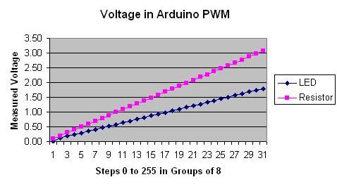
              That's how the Arduino fakes an analog signal on a digital pin. It writes and ANALOG value to a DIGITAL pin, varying the amount of time the voltage is on or off. It uses a value between 0 and 255 to get the results. For instance, a value of 127 (=255/2) means the voltage is on for 50% of the time. Since Arduino digital voltages are 0V and 5V, the effect is 2.5V at the digital pin. Any brightness can be chosen between 0 and 255, try it and see.
               For those who must know, the Arduino is sending square wave (not smooth sine waves) to the pin at 500 Hz, fast enough to fool even your digital multimeter. The full 5V is present when it is on, but it is only on part of the time. This PWM effect is another robotics fundamental that you will eventually have to understand completely. For now, it is enough to be aware that it works, and it is very precise. PWM "controls" the voltage much better than any analog dimmer switch ever built.
               How accurate is PWM? Well, it got me started with microcontrollers, that's how impressed I was. On December 1, 2010, I saw a demo of a toy electric train that was so realistic, I was floored. None of those jerky starts caused by rheostats. You can see the same video, called the Dawson Train on youTube. I didn't have a clue what was happening at the time, nor how relevant it was, you decide for yourself. The bottom line? Learn your PWM.


    /* January 25, 2011.
    * Experimental Serial Read & Display.
    * THIS CODE DOES NOT WORK, IT IS LEFT HERE AS A DISPLAY
    * OF AN INITIAL ATTEMPT THAT FAILED. Can you spot the errors?
    */

    /* The idea is to get a sensor, in this case a photoresistor
    * to send a stream of data to the IDE and see how it displays
    * under varying light conditions.
    */

    // Assign variables
    int Input = 0; // Assign input to analog pin 0
    float vValue; // Allow decimal readings
    // End assign variables.

    ////////////////////////////////////////////////////////////
    //Begin Main Program
    void setup()
    {
    Serial.begin(9600); // Turn on Serial Connection
    }

    void loop()
    {
    vValue = analogRead(Input); // Read the analog pin
    vValue = vValue / 5; // Step it down to 0-255
    Serial.println("You are here."); // Debug
    Serial.println(vValue); // Print to Serial monitor
    delay (1000); // Slow everything down
    }

    // End Main Program
    ///////////////////////////////////////////////////////////

    ///////////////////////////////////////////////////////////
    // Key entered by da Bassguy January 26, 2011
    // Adapted from several sources to read a sensor value.
    // This version does not work.
    // ///////////////////////////////////////////////////////


    SECOND VERSION (the successful version)


    // Experiment 008 - Photosensor Transistor Controlled Motor
    // Today is March 17, 2011
    // This sketch corresponds to Minutes 008 blog

    /* Adapted from several sources, this experiment is
    * designed to test the values read by the Arduino
    * analogRead statement and display them on the
    * Arduino serial monitor. Also, the input value
    * is to be converted from 10 bit to 8 bit to match
    * the range needed for PWM output. PWM is not tested
    * in this circuit.
    */

    ////////////////////////////////////////////////
    //Begin Initialization & Variables

    int PhotoResistorRead = 0; //The photocell pin (Input)
    int vPhotoCell; //Storage for photocell value
    // Note that the Arudino does not have to declare that
    // analog pins are input, that is the default for analog pins

    //End Initialization & Variables
    /////////////////////////////////////////////////

    /////////////////////////////////////////////////
    // Begin Main Program
    /////////////////////////////////////////////////

    void setup()
    {
    analogReference(DEFAULT); //Ensures we are reading 0 to 5 volts
    Serial.begin(9600); //Enable serial monitor read
    }
    //-----------------------------------------------------------------------
    void loop()
    {
    vPhotoCell = analogRead(PhotoResistorRead); //Read the photocell
    vPhotoCell = constrain(vPhotoCell, 300, 800); // Keeps values in range
    vPhotoCell = map (vPhotoCell, 330, 830, 0, 255); // convert to 8 bit
    Serial.println(vPhotoCell); //Display the value on serial monitor
    delay(500); //Slow things down
    }
    //-----------------------------------------------------------------------

    ////////////////////////////////////////////////////
    // END MAIN PROGRAM
    ////////////////////////////////////////////////////

    // Key entered by Anton da Bassguy 2011
    // Verified March 26, 2011.
    // Tested OK March 27, 2011
    // Corresponds to meeting minutes project 008
    // Schematic 008 - Read a photoresistor
    // Reviewed March 28, 2011
    ////////////////////////////////////////////////////

    Go BACK to Table of Contents

    009 SIMPLE RADIO CIRCUIT - work in progress.


    009 SIMPLE RADIO CIRCUIT - work in progress

    JANUARY 31, 2011    (See also Companion Blog )
    [Go BACK to Table of Contents] [ Next Experiment ] [ Last Experiment ]

                This is actually a combination of two separate circuits. The radio consists of a receiver section and an amplifier. The diagram here is only the reciever section. First is a simple radio receiver which will power a "crystal" earplug. Such a circuits are easy in the extreme, as soon as you connect the pieces they start working by themselves. I won't detail the operation, as schematics for such radios are available with all the documentation you'd ever need. Just build one, it will work.

              If you examine the first diagram, you will see that it is basically a coil and a capacitor connected to antenna and ground. It is powered by the radio waves in the air as they pass the antenna and induce a small electrical current. The coil has no "taps" and the capacitor is fixed, so the only way to "tune" this radio is to attach it to different antennas. I am probably going to use some type of variable coil and capacitor, but not right now.

                The earplugs are getting hard to find--and expensive. Earplugs have a tinny monoaural sound and are falling out of production as cell phone headphones dominate the market. However, headphones require more power than can be supplied sole by the radio circuit.
                Hence, my circuit contains an amplifier. Examine it closely, it is easy to understand once you recognize the components. The radio has no power supply, but the amplifier uses five volts. The weak radio signal is used to operate the single transistor base, allowing a larger current or voltage (I don't know yet) to drive a 2" speaker. This is my most ambitious project so far, please allow time for me to get it working. You may find more editorial comments at Tales From The Trailer Court which gives a less technical explanation but involves a lot more reading.

    FEBRUARY 5, 2011
                This project is more involved than I first imagined, but not because it is complicated. The reason is that I've taken care to study each component by itself and in combination. Wikipedia has an excellent article for novices, it is titled Electronic component . It is also a good read.

                The actual radio circuit is an amalgamation of several I've tinkered with, but this time I am learning why it works. The delay at this time is finding the proper parts, many of which have fallen out of availability due to Internet radio. I just located a tuning capacitor and have not yet figured out how to connect it. It is in a plastic casing with no obvious markings.

    Update April 5, 2012
                This project is now on permanent hold. In the end, it was the antenna technology that got too difficult. Also, building a radio from anything but a kit is, I found out the hard way, beyond the skills of a beginner. In the end, I dismantled most of the radio parts for use with other labs. The whole radio concept was chosen largely because I had no idea what constituted a reasonable goal.
                Radio is so refined, it is better to devote your energy into learning to use and code off-the-shelf gear, like the X-Bee, a short range FM controller. While a simple radio can be hand-made from spare parts, I now question if anything more complicated is worth the effort. Mind you, as the nearby picture shows, when the radio was on the agenda, we built some exceedingly high quality parts. Like this copper antenna coil.

    Go BACK to Table of Contents

    010 POTENTIOMETER TESTS


    010 POTENTIOMETER TESTS

    FEBRUARY 7, 2011    (See also Companion Blog )
    [Go BACK to Table of Contents] [ Next Experiment ] [ Last Experiment ]

               The purpose is to test the potentiometer effect on LED brightness, voltage, and motor speed. None of the various texts I've read explain the parallel, if any, between variable voltage and the effect of Pulse Width Modulation (PWM). I prefer to test the analog portions and components first.

    Theory:
              The pot (potentiomenter) should vary the voltage in the circuit, the brightness of the LED, and the speed of the motor. The circuit shows that potentiometer is in a position to vary the electric flow to the three components, the LED, the Voltmeter, and the motor. All segments of the circuit should be affected by the same changes.

    Practice:
              The voltage and LED did vary as predicted, but not the motor speed. Here is the measured effect of various resistor values in series with the voltmeter. The pot is not labeled, but I believe it goes from 0Ω to 10,000 Ω. I still include the static resistor, a holdover from having burned out too many LEDs.

              The table here is not pretty, but for some reason, this blog inserts a blank page of white space when I try to use table tags. (If you know the easy way to correct this, email me.)

    Fixed Resistor          Low Range                    High Range
     330Ω                    1.68V          1.88V          
    1000Ω                              1.68v          1.80V          
    4700Ω                              1.67V          1.72V          
    9400Ω                              1.66V              1.69V

    Conclusion:
              Turning the pot seems to vary the voltage in the LED segment of the circuit between very narrow limits. I note that the LED never did go out completely. The motor, however, was not at all behaving as expected. It ran at a constant speed or not at all throughout all pot settings. As the pot was the only variable here, I connected the pot and motor to the battery itself. This produced the same constant motor speed as without any resistance.

    Go BACK to Table of Contents

    011 TEST RANDOM PWM VALUES ON AN LED.


    011 TEST RANDOM PWM VALUES ON AN LED

    March 4, 2011    (See also Companion Blog )
    [Go BACK to Table of Contents] [ Next Experiment ] [ Last Experiment ]

               (Similar to experiment 007) This experiment will test the effects of random PWM on an LED, but the real goal is to use the LED to indicate changes, and to see if a multi-meter can be used to measure these changes. Research says that PWM varies the current while the voltage stays the same. I have no way to measure current at this time.
               As usual, the Arduino text assumes you know a lot of fine details, such as the PWM is controlled by a command called “analogWrite” and does not explain what you are writing. It seems to be a current, if so, they aren’t saying. I mean, how does one “write” a current? Hence this experiment.

               The code is adapted from a publication by Tod E. Kurt tod@todbot.com, but his code is not documented enough to indicate what parameters are changing. I am not including a breadboard schematic, as the circuit is quite simple and powered by the Arduino.


               Code: Matches Sketch A100414_08RandomPWM.

    Theory:
              The PWM has to vary something, so this experiment is very similar to experiment 007, where I did not ask enough questions. By allowing the code to vary the PWM at a very slow rate, I should be able to connect a multimeter and seek the correct readings. If the light gets brighter, some parameter must get larger, and the opposite should it get dimmer. We are seeking the elusive value that the PWM is affecting.

               You may note this is not the first time I’ve done a simple experiment in two steps. Wait, I can explain. I’m finding the documentation assumes I know too much. In this experiment, the first pass uses the random “delay” to prove that the Arduino is controlling the circuit rather than some wiring error or mistake on my part. The second pass puts in a fixed delay which I will attempt to measure.

    Practice:
              First pass, the random delay works perfectly, it even emulates the general flickering rate of a real candle. The random brightness, well, I’ll fiddle with that to see if I can get it to vary a little more, maybe I’m using too large a resistor (4700Ω). Yes, a smaller resistor brightened it up.

               Second pass, this time with the delay set to a strict 4 seconds, plenty of time for my multimeter to pick up the changes. There is a distinct correlation between the voltage and the brightness—but am I really measuring a PWM effect? Now I am confused, as I definitely read that it is the current that controls the brightness. I’ve experimented past my ability to understand what is happening. That’s not unusual.

               Also, because I’ve read that an ammeter must be connected in series to measure the current, I tried that configuration. Oddly, the LED never came on but the voltage still varied. There was no reading on any setting of my ammeter, it could be broken for all I know.


               This is frustrating, so I modified Sketch A100414_03FadeLEDinout (saved as A100414_03FadeLEDinout_A) to step up 8 “Arduino notches” at a time and recorded the voltage changes in 32 steps from 0 to 248 (close enough to the maximum of 255). Actually 31 steps, as the final reading got clipped by the loop reset. The voltage relationship to the LED brightness is completely linear, as shown by this graph, which measures the voltage at each step across the LED and the 1000Ω resistor. Here is a photo of the setup, I watch the LED change, note the voltage, and type it into the computer. You can see the multimeter leads drooping down and if you really look, you can see the orange LED to which the leads are clipped.

    Conclusion:
              The attempted measurement of PWM was a complete failure, there is not even enough data to substantiate that that the PWM was even the cause of the LED brightness variation. None of the textbooks I consulted covered this fine point, although they stress that PWM is very important.

               Authors such as Massimo Banzi go on about how PWM will dim an LED and they draw nice charts, to a one, they steadfastly refuse to state how it works in a real circuit. What is being varied and how does one measure it? And if it is activated by a “write” command, why is this not clearly specified before anything else?

               The breadboard schematic is virtually identical to Experiment 007 without the ammeter.

               Here is the code: (It is highly recommended you do NOT cut and paste this version.)


    /* Today is March 04, 2011
    * Experiment "Minutes 011" Effect of Random PWM values on LED
    * Adapted from Tod E. Kurt "Candlelight" sketch
    * See below to cross-reference (my) files
    */

    ////////////////////////////////////////////////
    //INITIALIZATION AND VARIABLES

    #define LED001 9 // set LED to pin 9
    int vLEDsetting = 0; // storage area for current LED value
    int vdelay = 0; // storage for the variable delay value
    /////////////////////////////////////////////////
    // Begin Main Program
    /////////////////////////////////////////////////

    void setup ()
    {
    pinMode(LED001, OUTPUT); // tell Arduino LED is output
    }

    void loop()
    {
    vLEDsetting = random(0,255); // generate random value >100<255
    analogWrite(LED001,vLEDsetting); // light the LED to that value

    // Here are two possible delays, operated by commenting out
    // the one you aren't testing:

    // Situation 1: variable delay
    // vdelay = random(150,300); // generate random delay
    // delay(vdelay); // delay in milliseconds

    // Situation 2: Fixed 4 second delay
    delay(4000);
    }

    ////////////////////////////////////////////////////
    // END MAIN PROGRAM
    ////////////////////////////////////////////////////

    // Key entered by Anton da Bassguy 2011
    // Reviewed March 04, 2011
    //
    // The wiring consisted of a LED and 4700 Ohm resistor
    // in series from Arduino pin 9 to chassis ground.
    // Actually, any ground will work with this voltage.
    ////////////////////////////////////////////////////

    Go BACK to Table of Contents

    Note the following information is also contained as comments in the IDE code:
    Cross references:
    Schematic: C:\Documents and Settings\Do Not Use\My Documents\8000 Series Files\8010 ARDUINO\1003 Circuit Diagram Jpegs
    Matches Sketch A100414_RandomPWM found in C:\Documents and Settings\Do Not Use\My Documents\8000 Series Files\8010 ARDUINO\3002 Arduino Saved Sketches