
March 4, 2011 (See also Companion Blog )
[Go BACK to Table of Contents] [ Next Experiment ] [ Last Experiment ]
(Similar to experiment 007) This experiment will test the effects of random PWM on an LED, but the real goal is to use the LED to indicate changes, and to see if a multi-meter can be used to measure these changes. Research says that PWM varies the current while the voltage stays the same. I have no way to measure current at this time.
As usual, the Arduino text assumes you know a lot of fine details, such as the PWM is controlled by a command called “analogWrite” and does not explain what you are writing. It seems to be a current, if so, they aren’t saying. I mean, how does one “write” a current? Hence this experiment.
The code is adapted from a publication by Tod E. Kurt tod@todbot.com, but his code is not documented enough to indicate what parameters are changing. I am not including a breadboard schematic, as the circuit is quite simple and powered by the Arduino.

Code: Matches Sketch A100414_08RandomPWM.
Theory:
The PWM has to vary something, so this experiment is very similar to experiment 007, where I did not ask enough questions. By allowing the code to vary the PWM at a very slow rate, I should be able to connect a multimeter and seek the correct readings. If the light gets brighter, some parameter must get larger, and the opposite should it get dimmer. We are seeking the elusive value that the PWM is affecting.
You may note this is not the first time I’ve done a simple experiment in two steps. Wait, I can explain. I’m finding the documentation assumes I know too much. In this experiment, the first pass uses the random “delay” to prove that the Arduino is controlling the circuit rather than some wiring error or mistake on my part. The second pass puts in a fixed delay which I will attempt to measure.
Practice:
First pass, the random delay works perfectly, it even emulates the general flickering rate of a real candle. The random brightness, well, I’ll fiddle with that to see if I can get it to vary a little more, maybe I’m using too large a resistor (4700Ω). Yes, a smaller resistor brightened it up.
Second pass, this time with the delay set to a strict 4 seconds, plenty of time for my multimeter to pick up the changes. There is a distinct correlation between the voltage and the brightness—but am I really measuring a PWM effect? Now I am confused, as I definitely read that it is the current that controls the brightness. I’ve experimented past my ability to understand what is happening. That’s not unusual.
Also, because I’ve read that an ammeter must be connected in series to measure the current, I tried that configuration. Oddly, the LED never came on but the voltage still varied. There was no reading on any setting of my ammeter, it could be broken for all I know.

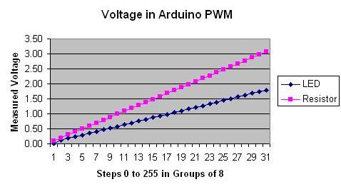
This is frustrating, so I modified Sketch A100414_03FadeLEDinout (saved as A100414_03FadeLEDinout_A) to step up 8 “Arduino notches” at a time and recorded the voltage changes in 32 steps from 0 to 248 (close enough to the maximum of 255). Actually 31 steps, as the final reading got clipped by the loop reset. The voltage relationship to the LED brightness is completely linear, as shown by this graph, which measures the voltage at each step across the LED and the 1000Ω resistor. Here is a photo of the setup, I watch the LED change, note the voltage, and type it into the computer. You can see the multimeter leads drooping down and if you really look, you can see the orange LED to which the leads are clipped.
Conclusion:
The attempted measurement of PWM was a complete failure, there is not even enough data to substantiate that that the PWM was even the cause of the LED brightness variation. None of the textbooks I consulted covered this fine point, although they stress that PWM is very important.
Authors such as Massimo Banzi go on about how PWM will dim an LED and they draw nice charts, to a one, they steadfastly refuse to state how it works in a real circuit. What is being varied and how does one measure it? And if it is activated by a “write” command, why is this not clearly specified before anything else?
The breadboard schematic is virtually identical to Experiment 007 without the ammeter.
Here is the code: (It is highly recommended you do NOT cut and paste this version.)
/* Today is March 04, 2011
 * Experiment "Minutes 011" Effect of Random PWM values on LED
 * Adapted from Tod E. Kurt "Candlelight" sketch
 * See below to cross-reference (my) files
 */

////////////////////////////////////////////////
//INITIALIZATION AND VARIABLES

#define LED001 9                // set LED to pin 9
int vLEDsetting = 0;              // storage area for current LED value
int vdelay = 0;                 // storage for the variable delay value
/////////////////////////////////////////////////
// Begin Main Program
/////////////////////////////////////////////////

void setup ()
{
  pinMode(LED001, OUTPUT);      // tell Arduino LED is output
}

void loop()
{
  vLEDsetting = random(0,255);  // generate random value >100<255
  analogWrite(LED001,vLEDsetting);  // light the LED to that value

// Here are two possible delays, operated by commenting out
// the one you aren't testing:

// Situation 1: variable delay
// vdelay = random(150,300);        // generate random delay
// delay(vdelay);                   // delay in milliseconds

// Situation 2: Fixed 4 second delay
   delay(4000);
}

////////////////////////////////////////////////////
// END MAIN PROGRAM
////////////////////////////////////////////////////

// Key entered by Anton da Bassguy 2011
// Reviewed March 04, 2011
//
// The wiring consisted of a LED and 4700 Ohm resistor
// in series from Arduino pin 9 to chassis ground.
// Actually, any ground will work with this voltage.
////////////////////////////////////////////////////

Go BACK to Table of Contents

Note the following information is also contained as comments in the IDE code:
Cross references:
Schematic: C:\Documents and Settings\Do Not Use\My Documents\8000 Series Files\8010 ARDUINO\1003 Circuit Diagram Jpegs
Matches Sketch A100414_RandomPWM found in C:\Documents and Settings\Do Not Use\My Documents\8000 Series Files\8010 ARDUINO\3002 Arduino Saved Sketches