March 13, 2011 (See also Companion Blog
[Go BACK to Table of Contents] [ Next Experiment ] [ Last Experiment ]
To investigate the behavior of a switch in a digital circuit. A moment’s thought first about three types of switches. One type is a throw switch, where you turn it on and it stays flipped in the on position, like a light switch. A second type is a momentary switch, where you press and release it but the effect continues, such as a computer power button. We accomplished this in Experiment 014. A third type is where you have to press and hold the switch, like a buzzer button.
It is the third case I’ll look at here. It seems to be the most useful type for much of what I plan to do, so time to make sure I thoroughly understand the operation. In a sense, this is a momentary switch, but continuous for as long as you hold it down.
This experiment borrows heavily from two sources, MakerShed1 Arduino 101 Add A Button and the Arduino Blinky Light Company introduced in Experiment 014, both available free on-line if you look for them. (The MakerShed video actually describes a situation where 0 Volts goes to ground, which I do not yet understand.)

Theory:
Since there are no relays or solenoids in this circuit, the idea is to have the computer interpret the external environment and control the operation according to that information. As usual, the trade off is that if the computer loses power, the entire assembly will not work. The advantage is that if we succeed, a single brand of switch can serve two different purposes.
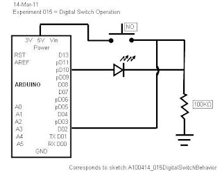
If you are not the sort to examine schematics very closely, this is one that is worth every brain cell you put into memorizing it. It seems simple, until you try to follow the electrical paths. Do not overlook this schematic or try to skip it, you’ll regret that later.
First look at the 5V path from the Arduino. It flows to the NO (normally open) switch and cannot get any further unless the switch is pressed.. The LED controlled by pin 10 (digital output) and will only change if pin 10 is HIGH, or 5V. But pin 10 will only be HIGH if pin 2 (digital input) is HIGH.
Notice, both these legs of the circuit run through a high resistance (100K). This threw me until I realized pin 2 must put out a tiny current into the circuit even when it is idle. This tiny current is limited by the large resistor, although some must trickle through to ground.
When the switch is depressed, the 5V power sees two possible paths, one through the large value resistor, or it can “push” an easier path back to pin 2. It takes this path of least resistance, literally. Pin 2 now reads HIGH, causing pin 10 to also go HIGH.
All the rest is programming. If the light is off, pressing the switch makes it go on until the switch is released. If it is already on, pressing the switch will make it go off. One switch, two different results without changing any physical components.
Practice:
Nothing yet. The circuit just sits there doing nothing. I suspect my wiring.
Conclusions:
At least I learned the concept of a larger current clobbering a smaller current. Or is it voltage? Either way, the resistor in the circuit is a very operative component, not just there to prevent LED burnout.
Here is the code:
// Experiment 015 - Digital Switch Behavior
// Today is March 13, 2011
// This sketch corresponds to Minutes 015 blog

/* This will investigate the operation of a digital
 * switch controlled by the Arduino.  The effect of
 * pressing the switch is determined by the computer
 * code, not the physical properties of the switch.
 */
////////////////////////////////////////////////
//Begin Initialization & Variables

int InputPin = 2;      //set the digital input to read pin 2
int OutputPin = 10;    //set the digital output to pin 10
int vVal = 0;          //storage location for reading pin 2
                       //value, initialized to zero

//End Initialization & Variables
/////////////////////////////////////////////////

/////////////////////////////////////////////////
// Begin Main Program
/////////////////////////////////////////////////

void setup()
{
  pinMode(InputPin, INPUT);
  pinMode(OutputPin, OUTPUT);
}
//-----------------------------------------------------------------------

void loop()
{
  vVal = digitalRead(InputPin);    //read the input pin
  if (vVal == LOW)                 //if it is low, change it so
  {digitalWrite(OutputPin,HIGH);}  //by default, the pin is high
//-----------------------------------------------------------------------
    else
    {
      digitalWrite(OutputPin,LOW); //when the switch is pressed,
    }                              //turn off the LED
//-----------------------------------------------------------------------
} // End void loop

////////////////////////////////////////////////////
// END MAIN PROGRAM
////////////////////////////////////////////////////

////////////////////////////////////////////////////
// Key entered by Anton da Bassguy 2011
// Verified March 14, 2011.
// Corresponds to meeting minutes project 015
// and schematic 015 - Digital Switch Behavior
////////////////////////////////////////////////////
1. MakerShed, which normally gets good marks from me, in this instance receives a “u”, my lowest possible rating. The reason is that their video disables the operational controls on my generic playback app. Once started, the video cannot be forwarded, paused, rewound or stopped without using Task Manager to disable the application.
Go BACK to Table of Contents
