
[Go BACK to Table of Contents] [ Next Experiment ] [ Last Experiment ]
This circuit was complicated by my inability to clearly visualize parallel breadboard circuits. Part of the purpose of this configuration was to finalize the concept in my brain.
Theory:
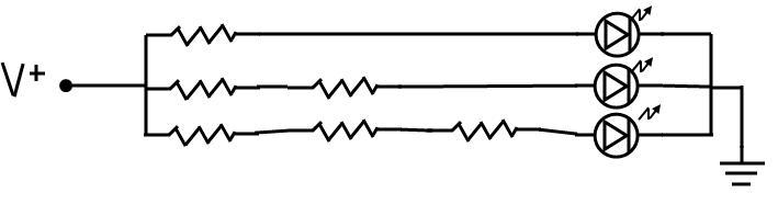
LEDs arranged in parallel with differing resistors should glow brighter or dimmer, depending on the total resistance. Thus, I chose six identical resistors, and wired them in strings of one, two, and three. At the end of each string is a LED. Look at this diagram. To me, it is obvious the last LED should be the dimmest.
When the power goes on, the brightest LED should be the leg with one resistor, next the LED with two, and the dimmest should be the LED with three. I also wired the breadboard so that there was a bare wire test point between each resistor to test the “voltage drop”.
Practice:
Nearly complete failure. The circuit lit up first try, but the brightness difference, if any, between the second and third LED was not distinguishable. I tried repositioning the LEDs in case there is such a thing as a bad one. No difference. Then I tried a different color. Still no difference.
Yet, there is a distinct difference in brightness with the one-resistor segment, therefore there must be a current difference in at least that leg. Why? Possibly the equation is non-linear and I need a far higher resistance on the third leg? The voltage across all three legs was 5V, so the lights should vary considerably since I used large (4700Ω) resistors. Either my thinking or the wiring is wrong. Soon, I will repeat this experiment using different resistors.
Conclusion:
I don’t know enough about resistors and how they function in parallel circuits. I should try this experiment again in a series arrangement. Actually, I would be happy if it turns out my logic was exactly opposite instead of somewhere in between, to show at least I was trying to think. The good news is I used the 7805 voltage regulator and am encouraged to solder a permanent supply. Later: if you go back and read the update to Experiment 2, you'll see I did just that. And it's a nice power supply, too.
January 27, 2011 (Update)
This experiment was repeated and for unknown reasons, partially successful today. Instead of resistors in series, I now have different resistors and I used 330Ω, 1kΩ and 4.7kΩ, all in parallel LED segments similar to the above. This time, I used the Arduino 5V supply and the Arduino ground. The LEDs lit up as expected, with the least resistance the brightest. Then for unknown reasons, the Arduino would die, that is, lose its communication with the computer and drop the communications port (Com 6 on my equipment) after a few seconds. It did this fifteen times.
As for the experiment, my original wiring or components were likely wrong. I suspect it takes an extremely high resistance to make a visible difference in brightness for the higher ratings and I would probably need a 10kΩ resistor to test this adequately. I now rate this experiment a success and the file closed.
May 1, 2011 (Update)
I was finally able to return to this experiment with the proper equipment, experience and knowledge to make it work. Here is a photo of the seven LEDs now varying in brightness due to gradually increasing resistors from left to right.

Later experience:
This circuit does not use the Arduino as a power supply, rather a good old 9V battery. I now understand that that the Arduino does not supply power continuously in every situation, that often the supply is dependent on the Arduino calling the correct pin continuously from within a loop, which is more trouble than it is worth for an analog experiment. But I had to learn it, so the effort was worthwhile.
Return later for details on how to duplicate this experiment. <<< I wrote that in haste. I think even a beginner should now be able to conduct this experiment without any panic. I leave the description as is so that you know even a schmuck like me can get it to eventually work. It is nothing but resistors and LEDs in parallel. It was months later I learned parallel is the way to get the same voltage (not the same current) across every leg of a circuit. Now, I have some choice words about voltage drops. Read on.
April 27, 2012 (Update)
Once again, the so-called "expert authors" left out so many important details that I no longer believe there is such a thing as a decent beginner's electronics manual. I say, dig some money out of your pocket, buy enough to get you started, and be prepared to mess up and destroy things. That's how I made the above experiment work, and look so nice, all wired cleanly and looking pretty. I dropped pieces, lost pieces, stepped on them, burned them out, burned my fingertips and drew blood on their leads. If you don't do the same, question your progress.

I won't detail my findings, but you can see from the following graphs that the voltage drop occurs in different places along the path. Here all I did was place the resistors before the LED in case A, and after the LED in case B. I had some baffling readings until I built the basic circuit shown in this experiment and did these measurements for myself. Is is important? I don't know, but I do know it caused me tribulation and was not even mentioned by the professionals. To be honest, I am sick and tired of all the half-baked authors out there who don't proof-read their own work and make getting started in electronics far more frustrating than it should be. They are there to sell books, not to teach the right things.
