April 1, 2011 (See also Companion Blog )
[Go BACK to Table of Contents] [ Next Experiment ] [ Last Experiment ]
I’ve narrowed down a basic pattern needed to turn an LED on and off using transistor control. While I do not yet know how to calculate the advantages, I know there is an upper limit to how many LEDs the Arduino can power. Therefore, to power LEDs above that limit, one must resort to transistors which require less internal power. In a single switch, only one action is needed to turn on a light. With transistors, the situation is much more involved. That is what I will look at now.
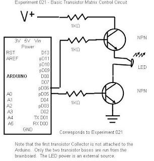
Here is the basic plan for a transistor control. I believe that no matter how complex the LED dot matrix becomes, in the end each of the individual circuits must follow the pattern below. Therefore, before I do anything complicated, I will design, build and test the basic circuit.
I discovered the principle of having to operate two pins to control a single LED in experiment 018. The idea is the same, but using transistors allows that two conditions must be met. The transistor controlling the 5V power supply must be set HIGH, and the transistor controlling the ground must also be set HIGH. At first this seems opposite to logic. But think about it, you are turning on the power and then turning on the ground. Both conditions must exist to light the LED. If both pins are HIGH or LOW, the LED will just sit there because no current will flow.
While none of the reading specifically states so, I am going design the LEDs to run off a separate 5V power supply and only the transistors will work from Arduino pin power. Each LED “switch” will thus require three resistors. One to limit the 5V power, and two to limit the Arduino signal to the two transistor bases. This is shown more clearly in the schematic below. The LED power supply is external, that is, not taken from the Arduino.

This is also an advance for me to use transistor switches, and to do so in combination. That experiment 018 really paid off here. The external power supply is also new, I have never used it in combination with the Arduino. Apparently this is a requirement for larger motor circuits, so I will test that here.
At the same time, the circuitry is not that complicated, so I will likely connect a series of the LEDs and transistors and attempt to get them to behave.
Theory:
The transistors act as switches in series. It looks like classic Boolean logic. The LED will only light when both switches are turned on, and that is accomplished by setting the transistor pins to HIGH. If either or both transistors are LOW, nothing will happen. If you are like me, it takes a moment’s thought to make this double switch logic comfortable.
Back in university, I think we called this arrangement an “AND gate” and this is the first time I’ve ever seen a real one. Because university isn’t a college, there was no practical side, so I can only hope I’m on the right track.
This “dual” control is especially important because of the dot matrix arrangement of the anodes (positive) and cathode (negative) linking of the LEDs. You’ll have to figure that out on your own, but think it through. All the positives are connected together. Without two separate transistors, it becomes impossible to target a single LED in a row or column.
We won’t have to worry about that here, but as soon as there is more than one LED, the two transistors will be crucial to success. So, let’s set up and test the real thing. Here is the Fritzing [diagram], but I’m having trouble getting some components to display, and I can’t find the command to stop the symbols from blocking each other.
Note: Fritzing has a nasty habit of only working when it wants to. It will come back saying a module is missing and reinstallation is the fix. That, Fritzing, is a lie.
Pause to think that in an LED dot matrix with 500 LEDs, this basic circuit must be duplicated 500 times – although there are certain economies from multiplexing, it will never be as simple as what is shown here. This experiment must succeed before there is any further progress with LED dot matrix design. Mind you, a failure might mean as with sensors, I had the basic concept wrong.
Practice:
The circuit worked, but there is a problem. When I say worked, it followed the exact rules of the Boolean logic. When both transistors were “HIGH”, the LED lit, but when both or any combination of transistors were “LOW”, the LED was out. That is the correct operation, although I did notice the same effect could be accomplished by leaving either transistor “HIGH” and flipping the other on and off.
Now the problem. The idea was to get the transistors to control the power from an external source, in this case a 9V battery. However, the LED worked and flashed when no external power was connected. Somehow, the transistor base voltage was getting through to the LED, which I could confirm by disconnecting the jumper. Research says that isn’t supposed to happen, so if this is something new, the glory is all mine [insert maniacal laugh here].
This is also an advance for me to use transistor switches, and to do so in combination. That experiment 018 really paid off here. The external power supply is also new, I have never used it in combination with the Arduino. Apparently this is a requirement for larger motor circuits, so I will test that here.
At the same time, the circuitry is not that complicated, so I will likely connect a series of the LEDs and transistors and attempt to get them to behave.
